
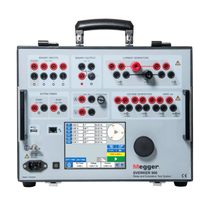
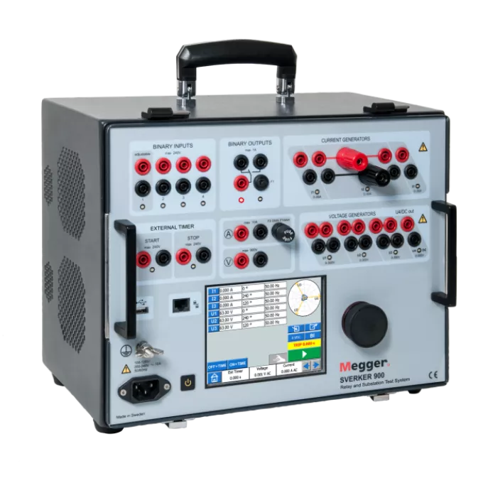
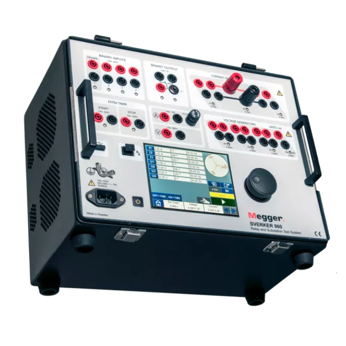
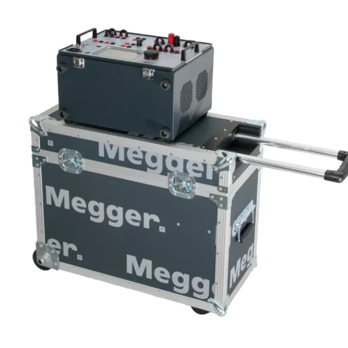
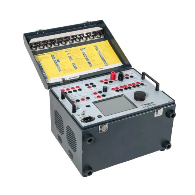
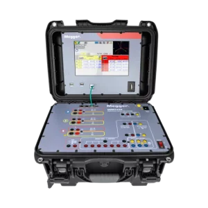
Megger SVERKER 900 Relay and Substation Test System

MPN: CR-19000
  • Designed for three-phase relay engineers
  • Three current and four voltage generators
  • Generates 105 A AC or 900 V AC single-phase
  • Standalone testing with LCD touch screen

Note: Price on application. Please call 01782 916228 or email sales@test4less.co.uk for further information.

Earn 0 points

Contact Us For Delivery Estimate

Why buy from Test4Less?

  • Designed for three-phase relay engineers
  • Three current and four voltage generators
  • Generates 105 A AC or 900 V AC single-phase
  • Standalone testing with LCD touch screen

Note: Price on application. Please call 01782 916228 or email sales@test4less.co.uk for further information.

Free Shipping

Spend over £100 on any new goods order and receive automatic free shipping

Rewards

Points make purchases! For every £1 spent, earn back 1p that can be spent on any future new goods purchase

Our Price Promise

We offer a Price Match Promise! Find an equivalent tester for a cheaper price on a competitor site, and we’ll do our best to match it

Express Delivery & Calibration

Express Delivery is currently unavailable for customers wishing to add calibration to their New Goods order. For more information, visit our Delivery Information page. 

Earn 0 points

Contact Us For Delivery Estimate

Customers also viewed

You may also like…

  • Megger SMRT46R Multi-Phase Relay Tester
    Contact Us For Delivery Estimate

    Megger SMRT46R Multi-Phase Relay Tester

    • Designed for multi-phase relay engineers.
    • Delivers up to 60 A and 319 VA per phase.
    • Integrated touch-screen control with RTMS.
    • Three VIGEN modules support six currents.
    Note: Price on application. Please call 01782 916228 or email sales@test4less.co.uk for further information.
  • Designed for three-phase relay engineers
  • Three current and four voltage generators
  • Generates 105 A AC or 900 V AC single-phase
  • Standalone testing with LCD touch screen


Megger SVERKER 900 Relay and Substation Test System

The Megger SVERKER 900 Relay and Substation Test System supports basic manual three-phase secondary testing of protection devices. It is designed for engineers working in electrical distribution substations, renewable power generation stations and industrial environments. Users can also perform selected primary tests by connecting the available sources in series or parallel.

Three current generators and four voltage generators provide flexible single-phase and three-phase operation. Each source allows separate adjustment of its amplitude, phase angle and frequency. In addition, the fourth voltage source can provide the reference voltage needed to simulate a busbar when testing numerical relays.

The Megger SVERKER 900 Relay and Substation Test System uses a 5.7-inch LCD touch screen and control knob for standalone field operation. Built-in storage saves tests and results, while the USB port allows files to be transferred between the instrument and a computer. Test files can be saved in CSV format for use with Excel.


Key Benefits
  • Supports manual single-phase and three-phase relay testing from one system
  • Allows current and voltage sources to operate separately, in parallel or in series
  • Generates up to 105 A AC for instantaneous-trip testing of overcurrent protection
  • Provides up to 900 V AC by connecting all four voltage generators in series
  • Uses a fourth voltage source to simulate a busbar reference for numerical relays
  • Provides standalone operation through the LCD touch screen and control knob
  • Changes current ranges automatically under load while maintaining the available compliance voltage
  • Saves test data internally and transfers CSV files through the USB connection
  • Measures current, voltage, resistance, impedance, phase angle, power and power factor
  • Uses regulated, galvanically separated sources to reduce the effect of supply and load changes


Common Applications

Megger SVERKER 900 Relay and Substation Test System is suitable for a range of testing, commissioning and maintenance tasks, including:

  • Commissioning and maintenance of distribution and generator substations
  • Testing protection relays
  • Testing electromechanical, static and numerical relays
  • Testing self-powered relays
  • Plotting current transformer excitation curves
  • Current and voltage transformer ratio testing
  • Burden measurement for current transformer circuits
  • Polarity and direction testing
  • Primary injection testing in switchgear
  • Checking SCADA annunciation, measurement values and wiring


Why Choose This Model?

Choose the Basic configuration for Main and Prefault-Fault testing, Standard when Ramping, Sequencer, CT Magnetization and MTT functions are required, or Expert where Impedance testing is also needed. Each configuration provides the SVERKER 900 current and voltage generation platform for standalone substation testing.


Product Comparison
Function SVERKER 900 Basic SVERKER 900 Standard SVERKER 900 Expert
Catalogue number CR-19090 CR-19092 CR-19094
Main Included Included Included
Prefault-Fault Included Included Included
Ramping, Sequencer and CT Magnetization Included Included
Prefault-Fault with MTT Included Included
MTT with reference curves Included; SVERKER Viewer licence required Included; SVERKER Viewer licence required
Impedance instrument Included
Soft-case option SVERKER 900 Standard with soft case, CR-19192


General Specifications
Specification Details
Product type Relay and substation test system
Current channels Three AC and DC current channels
Voltage channels Four AC and DC voltage channels
Output frequency DC and 10 Hz to 600 Hz
Display 5.7-inch LCD touch screen
Controls Touch screen and control knob
Data storage Built-in non-volatile storage for tests and test results
USB functions External keyboard and mouse connection, test-data storage and internal software updates
Saved file format CSV for use with Excel
Binary inputs Six galvanically separated dry or wet-contact inputs, maximum 240 V AC or 340 V DC
Binary output 250 V AC/DC, 1 A with 1 A fuse; 75 W resistive DC breaking capacity
Source isolation Current and voltage generators are galvanically separated from each other and from ground
Mains input 100 V to 240 V AC, 50/60 Hz
Maximum consumption 10 A current and 1800 VA power
CE directives LVD 2014/35/EU, EMC 2014/30/EU and RoHS 2011/65/EU
Shock and vibration IEC 60068-2-27 and IEC 60068-2-6
Voltage frequency ramp IEC 60255-181:2019


Measurement and Accuracy Specifications
Specification Details
Voltmeter measurement method AC True RMS and DC mean value
Voltmeter input and insulation 900 V input rating; 900 V and 1273 V peak insulation
DC voltage accuracy 0 V to 1 V: ±0.5% of reading + 3 mV
0 V to 10 V: ±0.5% of reading + 7 mV
0 V to 100 V: ±0.5% of reading + 30 mV
0 V to 900 V: ±0.5% of reading + 300 mV
AC voltage accuracy 0 V to 1 V: ±1% of reading + 5 mV
0 V to 10 V: ±1% of reading + 10 mV
0 V to 100 V: ±1% of reading + 50 mV
0 V to 900 V: ±1% of reading + 300 mV
Voltmeter resolution 1 mV
Measured frequency 10 Hz to 600 Hz; inaccuracy below 0.01%; resolution below 10 mHz
Ammeter measurement method AC True RMS and DC mean value
DC current accuracy 0 mA to 200 mA: ±0.5% of reading + 2 mA
0 A to 1.5 A: ±0.5% of reading + 3 mA
0 A to 10 A: ±0.5% of reading + 10 mA
AC current accuracy 0 mA to 200 mA: ±1% of reading + 2 mA
0 A to 1.5 A: ±1% of reading + 3 mA
0 A to 10 A: ±1% of reading + 20 mA
Ammeter resolution 0.1 mA
Power factor cosφ range from -0.01 capacitive through 1 to +0.01 inductive; resolution below 0.01; inaccuracy below 0.04
Measured phase angle 0° to 360°; resolution below 0.1°; inaccuracy below 0.8°
Impedance and power measurements AC: Z, R, X, P, S and Q
DC: R and P
Timer accuracy 0 ms to 50 ms: ≤1 ms
50 ms to 500 ms: ≤2 ms
Above 500 ms: ≤1%
Resolution: 1 ms
Voltage generator range Four-phase AC: 4 × 300 V
Four-channel DC: 4 × 300 V
Voltage generator power Four-phase AC: 4 × 125 VA maximum
Four-channel DC: 4 × 125 W maximum
Voltage output accuracy Typical: 0.03% of reading + 0.01% of range
Guaranteed: 0.05% of reading + 0.03% of range
Voltage output resolution 10 mV
Voltage output phase 0° to 360°; resolution 0.1°; inaccuracy below 0.5° at 50 Hz and 60 Hz
Voltage output frequency 10 Hz to 600 Hz; resolution 1 mHz; inaccuracy below 0.03% from 45 Hz to 66 Hz
Four voltage generators in parallel 300 V, 375 VA, 1.2 A maximum
100 V, 300 VA, 3.0 A maximum
67 V, 300 VA, 4.5 A maximum
Minimum external load: 7 Ω
Four voltage generators in series 900 V, 450 VA, 0.5 A maximum
400 V, 360 VA, 0.9 A maximum
268 V, 350 VA, 1.3 A maximum
Minimum external load: 100 Ω
Three-phase current range AC and DC: 3 × 35 A for at least 15 repetitions of 10 seconds on and 20 seconds off
AC and DC continuous: 3 × 20 A
Three-phase current power AC: 3 × 277 VA maximum
DC: 3 × 275 W maximum
Current output accuracy Typical below 200 mA: error below 0.5 mA
Typical from 200 mA to 35 A: 0.1% of reading + 0.01% of range
Guaranteed below 200 mA: error below 3 mA
Guaranteed from 200 mA to 35 A: 0.4% of reading + 0.01% of range
Current output resolution 1 mA
Current compliance voltage ≤50 V RMS
Parallel single-phase current output 2.6 A at 198 VA and 76 V, continuous
16 A at 816 VA and 51 V, continuous
26.5 A at 827 VA and 31.2 V, continuous
45.5 A at 819 VA and 18 V, continuous
60 A at 800 VA and 14 V, continuous
105 A at 721 VA and 7 V for at least 15 repetitions of 10 seconds on and 20 seconds off
Series single-phase current output 2.5 A at 403 VA and 161 V, continuous
8.2 A at 860 VA and 105 V, continuous
17.6 A at 827 VA and 47 V, continuous


Mechanical and General Information
Specification Details
Application environment High-voltage substations and industrial environments
Operating temperature 0°C to +50°C
Storage and transport temperature -40°C to +70°C
Humidity 5% to 95% RH, non-condensing
Maximum operating altitude 2000 m
Instrument dimensions 350 × 270 × 220 mm
Flight case with wheels dimensions 615 × 295 × 500 mm
Flight case dimensions 620 × 295 × 365 mm
Instrument weight 15.2 kg
Weight with accessories and wheeled flight case 29.2 kg
Weight with accessories and GD-00182 flight case 24.1 kg
Available interface languages Czech, English, French, German, Spanish, Swedish, Polish, Romanian, simplified Chinese and traditional Chinese
Optional LCA1 dimensions 110 × 64 × 28 mm
Optional LCA2 dimensions 110 × 64 × 44 mm
Optional low-current adapter 0.2 kg; 5 A maximum input


Specification Notes
  • Specifications apply with a resistive load, a 170 V to 240 V supply, an ambient temperature of +25°C ±3°C and a 30-minute warm-up within the 15 Hz to 70 Hz range.
  • Voltage output phase and frequency accuracy applies to separate U1, U2, U3 and U4/DC outputs with a resistive load above 2000 Ω.
  • Current output phase and frequency accuracy applies with a resistive load of 0.08 Ω or less and current of at least 0.15 A. Series-connected current generators are limited to 18 A and 70 Hz.


What’s Included
  • Megger SVERKER 900 Relay and Substation Test System
  • Standard test cable set, GA-00030
  • Earth cable, GA-00200
  • 900 V cable set, GA-00036
  • Flight case with wheels, GD-00185
  • Ten jumpers stored in the case lid
  • Touch-screen pen
  • Quick guide

For the SVERKER 900 Standard with soft case, the flight case is replaced by the soft case.

Optional extras:

  • SVERKER Viewer PC Software, CR-8101X
  • Flight case, GD-00182
  • Soft Case Combi, GD-00900
  • Low current adapter, CR-90010
  • Calibration box, CR-91010
  • SVERKER900 LPIT101 low-level adapter, CR-92090


Meta Description

Megger SVERKER 900 Relay and Substation Test System for manual three-phase relay tests with outputs up to 105 A AC and 900 V AC.

Megger SVERKER 900 Relay and Substation Test System

The Megger SVERKER 900 Relay and Substation Test System supports basic manual three-phase secondary testing of protection devices. It is designed for engineers working in electrical distribution substations, renewable power generation stations and industrial environments. Users can also perform selected primary tests by connecting the available sources in series or parallel.

Three current generators and four voltage generators provide flexible single-phase and three-phase operation. Each source allows separate adjustment of its amplitude, phase angle and frequency. In addition, the fourth voltage source can provide the reference voltage needed to simulate a busbar when testing numerical relays.

The Megger SVERKER 900 Relay and Substation Test System uses a 5.7-inch LCD touch screen and control knob for standalone field operation. Built-in storage saves tests and results, while the USB port allows files to be transferred between the instrument and a computer. Test files can be saved in CSV format for use with Excel.


Key Benefits
  • Supports manual single-phase and three-phase relay testing from one system
  • Allows current and voltage sources to operate separately, in parallel or in series
  • Generates up to 105 A AC for instantaneous-trip testing of overcurrent protection
  • Provides up to 900 V AC by connecting all four voltage generators in series
  • Uses a fourth voltage source to simulate a busbar reference for numerical relays
  • Provides standalone operation through the LCD touch screen and control knob
  • Changes current ranges automatically under load while maintaining the available compliance voltage
  • Saves test data internally and transfers CSV files through the USB connection
  • Measures current, voltage, resistance, impedance, phase angle, power and power factor
  • Uses regulated, galvanically separated sources to reduce the effect of supply and load changes


Common Applications

Megger SVERKER 900 Relay and Substation Test System is suitable for a range of testing, commissioning and maintenance tasks, including:

  • Commissioning and maintenance of distribution and generator substations
  • Testing protection relays
  • Testing electromechanical, static and numerical relays
  • Testing self-powered relays
  • Plotting current transformer excitation curves
  • Current and voltage transformer ratio testing
  • Burden measurement for current transformer circuits
  • Polarity and direction testing
  • Primary injection testing in switchgear
  • Checking SCADA annunciation, measurement values and wiring


Why Choose This Model?

Choose the Basic configuration for Main and Prefault-Fault testing, Standard when Ramping, Sequencer, CT Magnetization and MTT functions are required, or Expert where Impedance testing is also needed. Each configuration provides the SVERKER 900 current and voltage generation platform for standalone substation testing.

Product Comparison
Function SVERKER 900 Basic SVERKER 900 Standard SVERKER 900 Expert
Catalogue number CR-19090 CR-19092 CR-19094
Main Included Included Included
Prefault-Fault Included Included Included
Ramping, Sequencer and CT Magnetization Included Included
Prefault-Fault with MTT Included Included
MTT with reference curves Included; SVERKER Viewer licence required Included; SVERKER Viewer licence required
Impedance instrument Included
Soft-case option SVERKER 900 Standard with soft case, CR-19192


General Specifications
Specification Details
Product type Relay and substation test system
Current channels Three AC and DC current channels
Voltage channels Four AC and DC voltage channels
Output frequency DC and 10 Hz to 600 Hz
Display 5.7-inch LCD touch screen
Controls Touch screen and control knob
Data storage Built-in non-volatile storage for tests and test results
USB functions External keyboard and mouse connection, test-data storage and internal software updates
Saved file format CSV for use with Excel
Binary inputs Six galvanically separated dry or wet-contact inputs, maximum 240 V AC or 340 V DC
Binary output 250 V AC/DC, 1 A with 1 A fuse; 75 W resistive DC breaking capacity
Source isolation Current and voltage generators are galvanically separated from each other and from ground
Mains input 100 V to 240 V AC, 50/60 Hz
Maximum consumption 10 A current and 1800 VA power
CE directives LVD 2014/35/EU, EMC 2014/30/EU and RoHS 2011/65/EU
Shock and vibration IEC 60068-2-27 and IEC 60068-2-6
Voltage frequency ramp IEC 60255-181:2019


Measurement and Accuracy Specifications
Specification Details
Voltmeter measurement method AC True RMS and DC mean value
Voltmeter input and insulation 900 V input rating; 900 V and 1273 V peak insulation
DC voltage accuracy 0 V to 1 V: ±0.5% of reading + 3 mV
0 V to 10 V: ±0.5% of reading + 7 mV
0 V to 100 V: ±0.5% of reading + 30 mV
0 V to 900 V: ±0.5% of reading + 300 mV
AC voltage accuracy 0 V to 1 V: ±1% of reading + 5 mV
0 V to 10 V: ±1% of reading + 10 mV
0 V to 100 V: ±1% of reading + 50 mV
0 V to 900 V: ±1% of reading + 300 mV
Voltmeter resolution 1 mV
Measured frequency 10 Hz to 600 Hz; inaccuracy below 0.01%; resolution below 10 mHz
Ammeter measurement method AC True RMS and DC mean value
DC current accuracy 0 mA to 200 mA: ±0.5% of reading + 2 mA
0 A to 1.5 A: ±0.5% of reading + 3 mA
0 A to 10 A: ±0.5% of reading + 10 mA
AC current accuracy 0 mA to 200 mA: ±1% of reading + 2 mA
0 A to 1.5 A: ±1% of reading + 3 mA
0 A to 10 A: ±1% of reading + 20 mA
Ammeter resolution 0.1 mA
Power factor cosφ range from -0.01 capacitive through 1 to +0.01 inductive; resolution below 0.01; inaccuracy below 0.04
Measured phase angle 0° to 360°; resolution below 0.1°; inaccuracy below 0.8°
Impedance and power measurements AC: Z, R, X, P, S and Q
DC: R and P
Timer accuracy 0 ms to 50 ms: ≤1 ms
50 ms to 500 ms: ≤2 ms
Above 500 ms: ≤1%
Resolution: 1 ms
Voltage generator range Four-phase AC: 4 × 300 V
Four-channel DC: 4 × 300 V
Voltage generator power Four-phase AC: 4 × 125 VA maximum
Four-channel DC: 4 × 125 W maximum
Voltage output accuracy Typical: 0.03% of reading + 0.01% of range
Guaranteed: 0.05% of reading + 0.03% of range
Voltage output resolution 10 mV
Voltage output phase 0° to 360°; resolution 0.1°; inaccuracy below 0.5° at 50 Hz and 60 Hz
Voltage output frequency 10 Hz to 600 Hz; resolution 1 mHz; inaccuracy below 0.03% from 45 Hz to 66 Hz
Four voltage generators in parallel 300 V, 375 VA, 1.2 A maximum
100 V, 300 VA, 3.0 A maximum
67 V, 300 VA, 4.5 A maximum
Minimum external load: 7 Ω
Four voltage generators in series 900 V, 450 VA, 0.5 A maximum
400 V, 360 VA, 0.9 A maximum
268 V, 350 VA, 1.3 A maximum
Minimum external load: 100 Ω
Three-phase current range AC and DC: 3 × 35 A for at least 15 repetitions of 10 seconds on and 20 seconds off
AC and DC continuous: 3 × 20 A
Three-phase current power AC: 3 × 277 VA maximum
DC: 3 × 275 W maximum
Current output accuracy Typical below 200 mA: error below 0.5 mA
Typical from 200 mA to 35 A: 0.1% of reading + 0.01% of range
Guaranteed below 200 mA: error below 3 mA
Guaranteed from 200 mA to 35 A: 0.4% of reading + 0.01% of range
Current output resolution 1 mA
Current compliance voltage ≤50 V RMS
Parallel single-phase current output 2.6 A at 198 VA and 76 V, continuous
16 A at 816 VA and 51 V, continuous
26.5 A at 827 VA and 31.2 V, continuous
45.5 A at 819 VA and 18 V, continuous
60 A at 800 VA and 14 V, continuous
105 A at 721 VA and 7 V for at least 15 repetitions of 10 seconds on and 20 seconds off
Series single-phase current output 2.5 A at 403 VA and 161 V, continuous
8.2 A at 860 VA and 105 V, continuous
17.6 A at 827 VA and 47 V, continuous


Mechanical and General Information
Specification Details
Application environment High-voltage substations and industrial environments
Operating temperature 0°C to +50°C
Storage and transport temperature -40°C to +70°C
Humidity 5% to 95% RH, non-condensing
Maximum operating altitude 2000 m
Instrument dimensions 350 × 270 × 220 mm
Flight case with wheels dimensions 615 × 295 × 500 mm
Flight case dimensions 620 × 295 × 365 mm
Instrument weight 15.2 kg
Weight with accessories and wheeled flight case 29.2 kg
Weight with accessories and GD-00182 flight case 24.1 kg
Available interface languages Czech, English, French, German, Spanish, Swedish, Polish, Romanian, simplified Chinese and traditional Chinese
Optional LCA1 dimensions 110 × 64 × 28 mm
Optional LCA2 dimensions 110 × 64 × 44 mm
Optional low-current adapter 0.2 kg; 5 A maximum input


Specification Notes
  • Specifications apply with a resistive load, a 170 V to 240 V supply, an ambient temperature of +25°C ±3°C and a 30-minute warm-up within the 15 Hz to 70 Hz range.
  • Voltage output phase and frequency accuracy applies to separate U1, U2, U3 and U4/DC outputs with a resistive load above 2000 Ω.
  • Current output phase and frequency accuracy applies with a resistive load of 0.08 Ω or less and current of at least 0.15 A. Series-connected current generators are limited to 18 A and 70 Hz.

SVERKER 900 Data Sheets & Manuals

SVERKER 900 Data Sheet

SVERKER 900 Brochure

SVERKER 900 Technical Guide

SVERKER 900 User Guide


SVERKER 900 Software & Firmware Updates

Viewer Software

SVERKER Software


What’s Included
  • Megger SVERKER 900 Relay and Substation Test System
  • Standard test cable set, GA-00030
  • Earth cable, GA-00200
  • 900 V cable set, GA-00036
  • Flight case with wheels, GD-00185
  • Ten jumpers stored in the case lid
  • Touch-screen pen
  • Quick guide

For the SVERKER 900 Standard with soft case, the flight case is replaced by the soft case.

Optional Extras
  • SVERKER Viewer PC Software, CR-8101X
  • Flight case, GD-00182
  • Soft Case Combi, GD-00900
  • Low current adapter, CR-90010
  • Calibration box, CR-91010
  • SVERKER900 LPIT101 low-level adapter, CR-92090

Ask a question

Ask a question | Product pages